- 電化學相關(5)
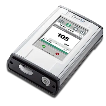
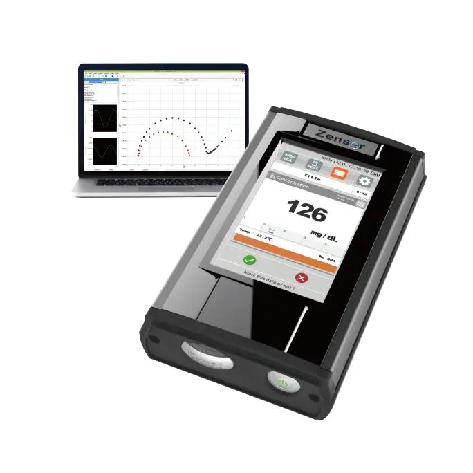
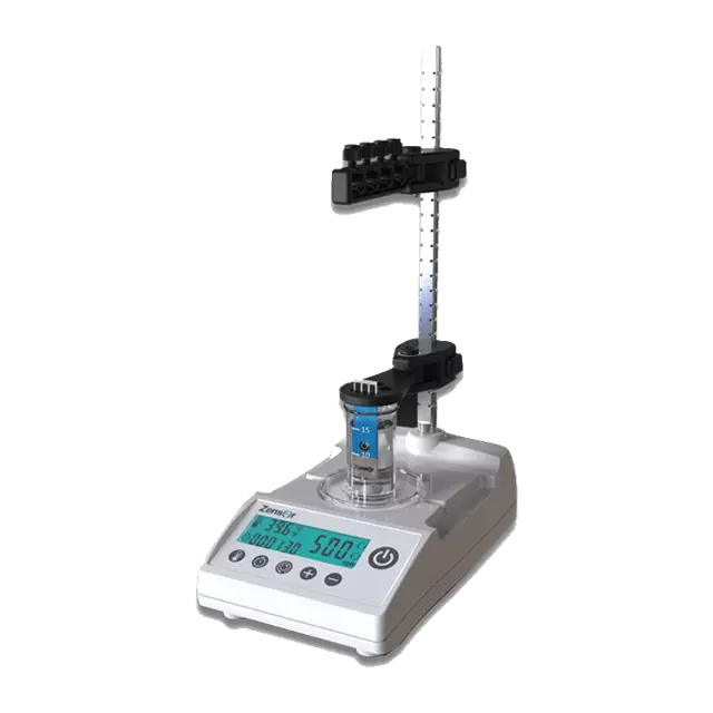
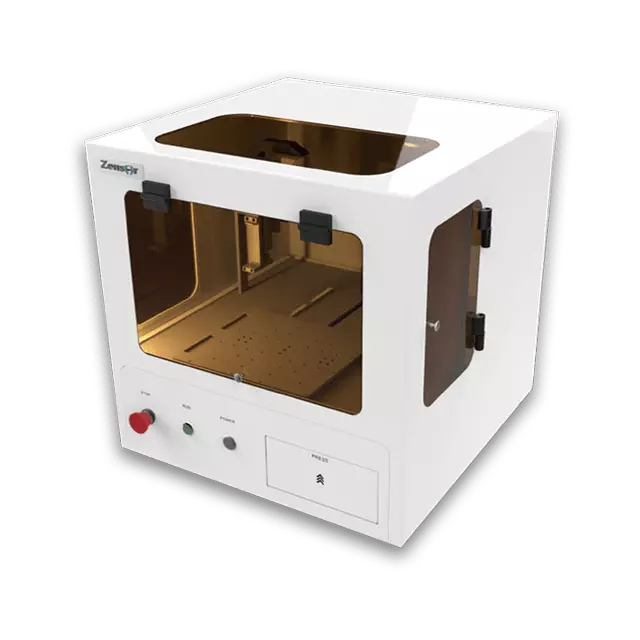
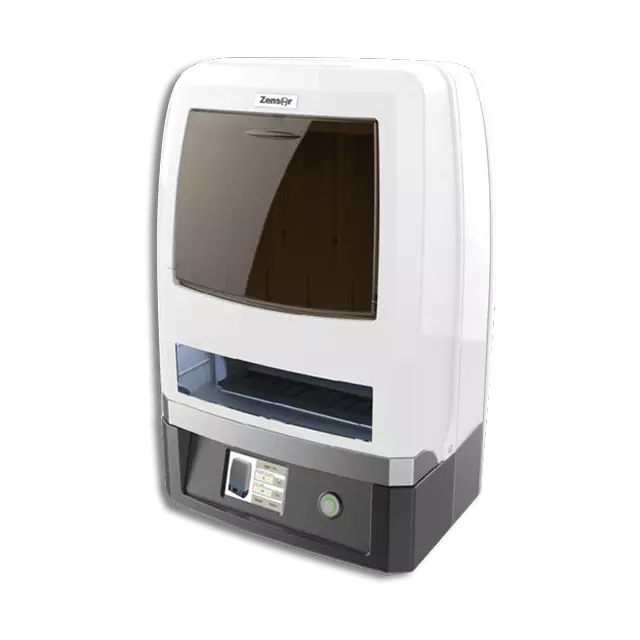
- 化學感測器實擬分析儀 - Zensor Simulator(4)
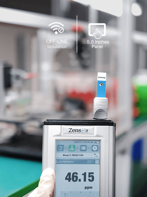
- ECAS100
- ACIP100
- Optical + EC
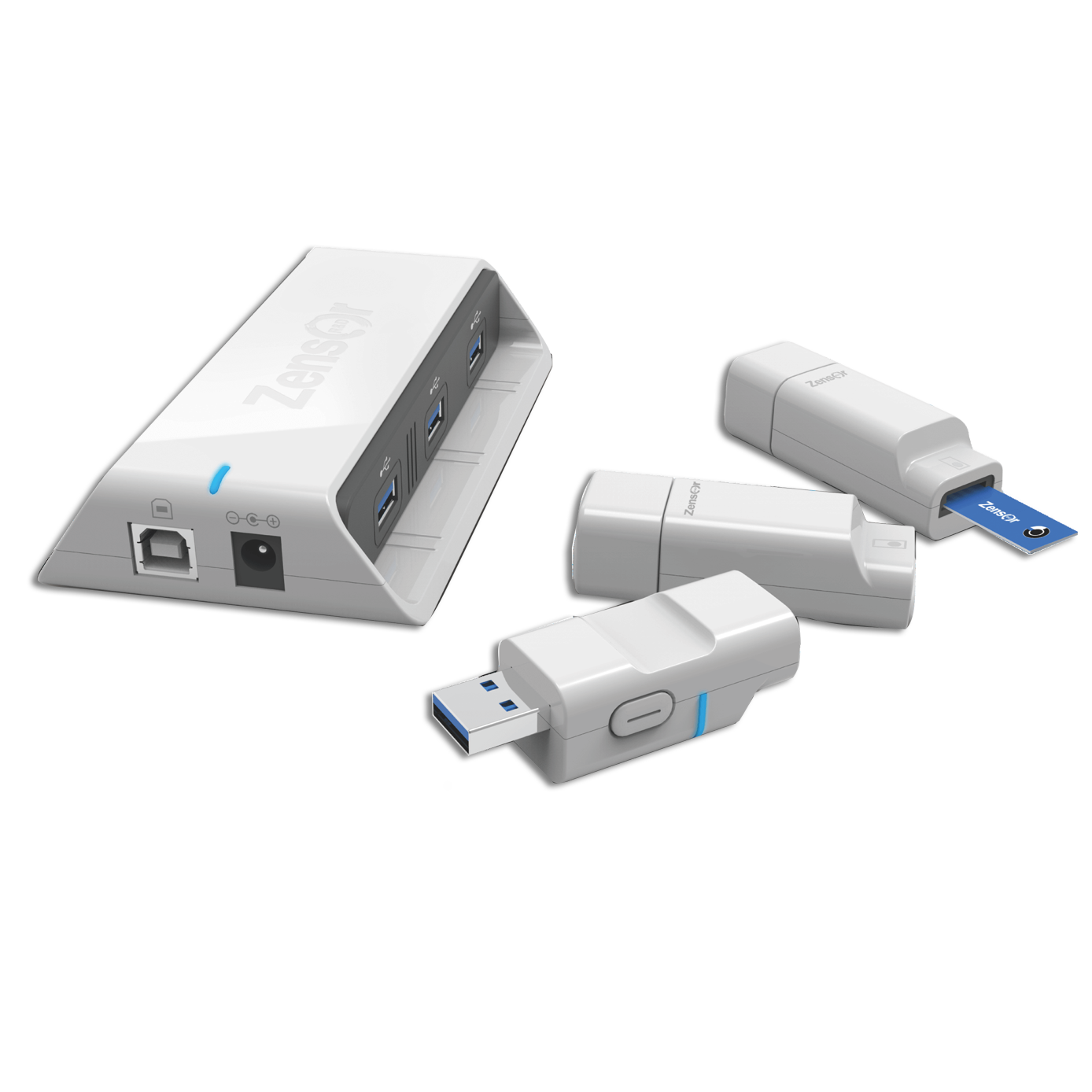
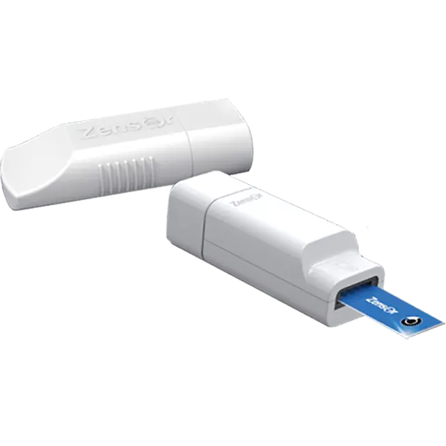
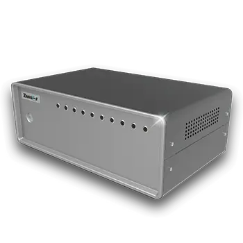
- 電化學偵測器 - Zensor ECD(1)
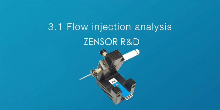
- SF100
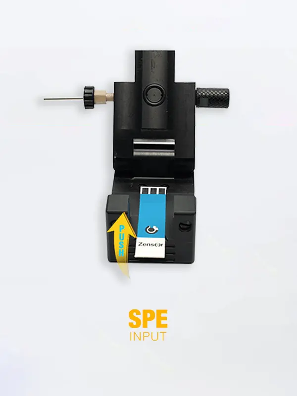
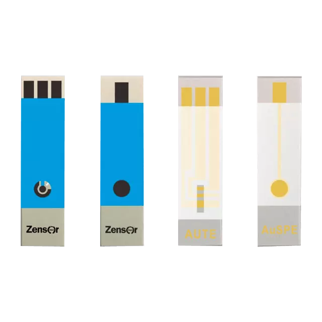
- 網版印刷電極 - Zensor SPE(7)
- 電極客製服務
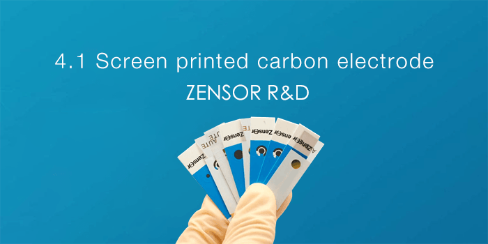
- TE100 碳三電極
- SE100 碳單電極
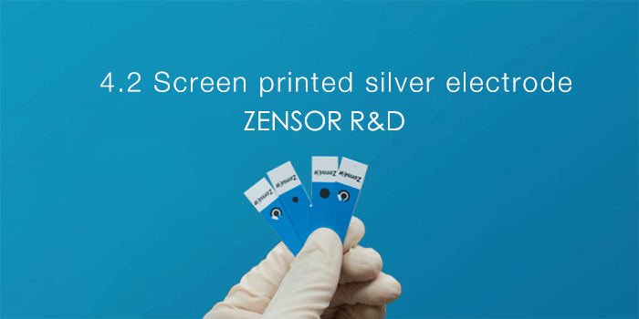
- AG100 銀電極
- AUSE100 金電極
- SAUTE100 金電極
- AUTE200 金電極
- 無線&多通道恆電位儀 / 電化學分析儀 - Zensor MCP(2)
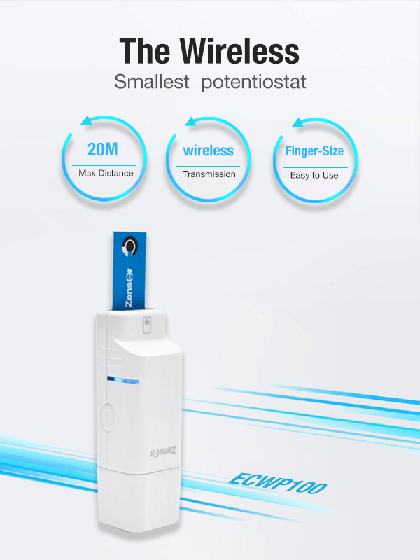
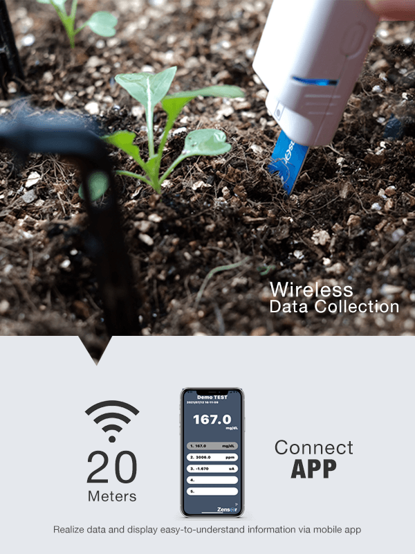
- ECWP100
- MCP100
- 其他產品(3)
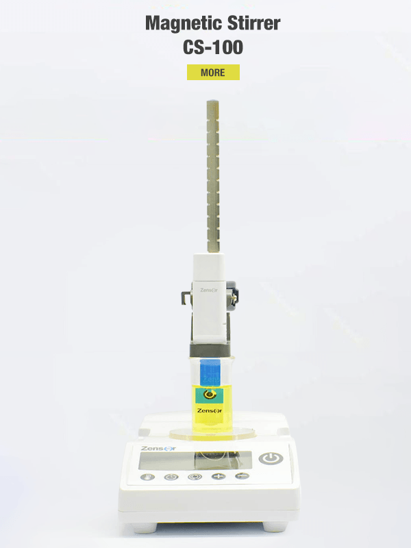
- CS100
- CM100
- CT100
- 化學感測器實擬分析儀 - Zensor Simulator(4)
- 相關公司(8)